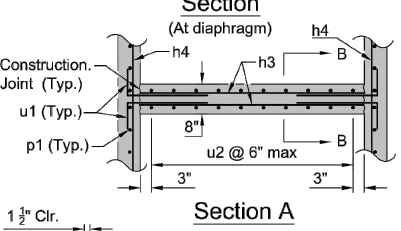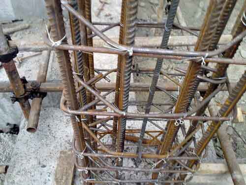

Note, however, that overlap requirements vary with both rebar size and the specific structural application. Based on the simple formula adopted by ACI 318-14 7, the general expression of the tension lap-splice strength has the following form: (2) f sp C f y K1 / f c K 2 where fps is the tension splice strength C is the constant of statistical analysis chosen with the purpose of making the average numerical to propose splice strength ratios. From a structural point of view, the most critical aspect of a lap splice is the overlap length. Replacement conductors shall be of the same voltage and current rating as the original conductor. The lap splice, as the name suggests, is created by overlapping two lengths of rebar, then wiring them together.

Western Union splices are used for solid conductors.Ĭable ties/lacing shall not be installed across the splice/solder sleeve body, unless sufficient protection is provided to prevent compression damage to the termination and/or to the insulation of adjacent conductors. Tubing is tightly shrunk, with proper strain relief, overlap and no exposed conductive surfaces. The termination is fully wetted, smooth and shiny. Tubing is tightly shrunk with proper strain relief, overlap and no exposed conductive surfaces. Tubing is tightly shrunk with proper strain relief. The second type is through the use of a beam splice for linearly aligned. The Department will allow field splices in place of laps. The compression lap splice criteria in ACI 318-081were based on just 11 column tests2that were conducted more than 40 years ago, using concrete with a maximum compressive strength of 29.0 MPa. The termionation is fully wetted, smooth and shiny. Column to column connectionsThe easiest answer it likely to wrap a hollow. All of that part of the structure below the bearings of simple and. Tubing is tightly shrunk, with proper strain relief, overlap and no exposed conductive surfaces. (f) Types of Seed Mixes - Seed mixes, quantities, standards, seeding rates, and other information will be included in the. Conductor(s) exhibit proper bend radius and strain relief. Overlaps meet minimum electrical spacing, while providing strain relief. Indents are symmetrical and centered on the crimp barrel. The contact has been deformed only by tool indenters. Introduction When reinforcement is spliced within a concrete beam, it is necessary to overlap bars by a sufficient length for transmission of tensile stresses between bars, through concrete without bond failure. Final assembly profile shall not impact form, fit or function.Ĭable ties/lacing shall be installed at both ends of a splice or solder sleeve, but placement shall not violate stress relief requirements.

The location of splices shall be staggered to minimize the increase in profile to the harness. The splice exhibits a smooth profile, proper strain relief, and is located in an area of the harness not subjected to flexure. See Section 4.01 "Cable and Harness, General Requirements", and Section 6.01 "Through-Hole Soldering, General Requirements", for common accept/reject criteria. CABLE AND HARNESS SPLICES CABLE AND HARNESSĪ splice is the joining of two or more conductors together in a manner that results in a permanent electrical termination and mechanical bond, and may be completed by either crimp or solder process.


 0 kommentar(er)
